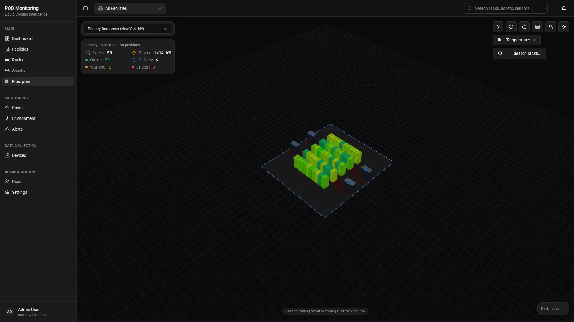
A Power Management System (PMS) is the software and hardware infrastructure responsible for monitoring, recording, and in some configurations controlling the electrical chain of a data centre facility. Its scope extends from the utility intake — transformers, main low-voltage switchgear, and automatic transfer switches — through uninterruptible power supply (UPS) systems and power distribution units (PDUs) to individual circuit breakers at the rack level.
Key facts
- A PMS monitors electrical infrastructure; a Building Management System (BMS) monitors environmental infrastructure. The two systems are distinct and complementary.
- Primary metered quantities: voltage, current, frequency, power factor, real power (kW), apparent power (kVA), reactive power (kVAR), and energy consumption (kWh).
- EU Directive 2023/1791 (recast EED) mandates annual energy and PUE reporting for data centres with IT loads above 500 kW. The PMS is the primary data source for this obligation.
- Communication protocols in common use: Modbus RTU, Modbus TCP, SNMP, BACnet IP, BACnet MS/TP, MQTT, DNP3, and IEC 61850.
- A three-tier architecture — field devices, edge concentrators, and central management — is the standard deployment model. The edge tier is responsible for local alarm evaluation independent of wide-area network connectivity.
BMS and PMS Integration
PODTECH delivers BMS/PMS integration across colocation, enterprise, and hyperscale data centre environments.
Contact the teamContents
- Definition and scope
- Metered data types
- System architecture
- Communication protocols
- Alarm management
- EED and regulatory reporting
- Integration with BMS
- Integration with NMS
- PODVIEW as the monitoring layer
- Specification considerations
Definition and scope
A Power Management System is the dedicated software and communications infrastructure that provides visibility into electrical performance across all power-consuming and power-distributing assets on a data centre site. The term encompasses both the field hardware (meters, sensors, communication gateways) and the software platform that collects, stores, and presents the resulting data.
The PMS boundary begins at the electrical point of common coupling — typically the high-voltage substation intake or transformer secondary — and extends to the lowest metered circuit on the distribution network. In dense deployments this includes individual PDU outlet-level metering at the rack.
The complementary system is the Building Management System (BMS), which governs environmental parameters: temperature, humidity, airflow, access control, and fire suppression. The distinction between BMS and PMS scope is a common source of specification ambiguity on new data centre projects. The two systems share no hardware but must share data for combined operational visibility and regulatory reporting.
A mature PMS provides four categories of capability: continuous metering, event detection and classification, historical data retention, and — where specified — automated or operator-initiated control of power infrastructure.
Metered data types
The following quantities are standard across data centre PMS deployments. All values are collected per phase on three-phase circuits and at the aggregate feed level.
| Quantity | Unit | Primary use |
|---|---|---|
| Voltage (L-N, L-L) | V | Supply quality, threshold monitoring |
| Current | A | Load monitoring, circuit capacity management |
| Frequency | Hz | Grid stability, UPS bypass synchronisation |
| Power factor | dimensionless (0–1) | Efficiency, reactive power penalty avoidance |
| Real power | kW | Instantaneous load, PUE numerator |
| Apparent power | kVA | UPS and generator sizing |
| Reactive power | kVAR | Power factor correction sizing |
| Energy consumption | kWh | Billing, ISO 50001, EED reporting |
| Total harmonic distortion | % THD | Supply quality, sensitive equipment protection |
| Ground fault current | mA | Safety, insulation monitoring |
Polling intervals vary by criticality. Main incomer, UPS, and generator circuits are typically polled at one-second intervals. Distribution board and PDU circuits may use five- to fifteen-second intervals depending on PMS historian capacity and network bandwidth. Energy accumulation registers (kWh counters) are typically read at fifteen-minute intervals to align with half-hourly electricity settlement periods.
Power quality events — voltage sags, swells, transients, and harmonic disturbances — require waveform capture at sampling rates of 256 or more samples per cycle (12.8 kHz at 50 Hz). General-purpose PMS platforms do not typically support waveform capture; a dedicated Power Quality Analyser (PQA) is required for sub-cycle event recording.
System architecture
Data centre power management systems are structured across three logical tiers: field devices, edge concentrators, and central management. In managed-services deployments a fourth tier — a multi-site monitoring platform — sits above the central management layer.
Tier 1 — Field devices are the physical assets that generate metering data. Each device exposes data through one or more communication interfaces (see Protocol coverage below). Devices that lack native network interfaces require a serial gateway or protocol converter at the edge tier.
Tier 2 — Edge concentrator aggregates data from multiple field devices, normalises protocol formats, buffers data during upstream connectivity loss, and executes local alarm logic. The local alarm logic function is operationally significant: when all threshold evaluation runs exclusively on the central server, any wide-area network failure between the site and the server silences all alarms for the duration of the outage. An edge concentrator with local alarm evaluation maintains protection independently of central connectivity. PODTECH deploys the POD-A1 hardware unit in this role across data centre and industrial environments.
Tier 3 — Central management hosts the PMS server application, time-series historian, reporting engine, and operator dashboards. In a managed-services model this tier connects northbound to a multi-site monitoring platform that provides consolidated visibility across multiple facilities.
The edge concentrator tier is the component most commonly removed from PMS specifications to reduce upfront cost. The operational consequence — loss of alarm coverage during any WAN or LAN fault — is frequently not apparent until the first network outage occurs during a live electrical event.
Communication protocols
Data centre electrical equipment uses a range of communication protocols, and a site will typically contain devices from multiple generations using different interfaces. PMS platform selection must account for the complete protocol matrix of the installed asset base.
Modbus RTU
Serial protocol over RS-485. Prevalent in legacy UPS units, power meters, and switchgear from all major manufacturers. Register-based data model; each device is addressed by station number. Maximum network speed is 115,200 baud; typical deployment uses 9,600 or 19,200 baud. A multi-drop bus supports up to 32 devices per segment without repeaters. Any PMS operating in a brownfield facility must include Modbus RTU driver support.
Modbus TCP
The same Modbus register model encapsulated over TCP/IP on port 502. Enables faster polling intervals and integrates with standard Ethernet infrastructure. Modbus RTU and Modbus TCP share a common data model; most PMS platforms use a unified driver covering both transport variants. Devices with both serial and Ethernet interfaces may expose Modbus RTU on one interface and Modbus TCP on the other simultaneously.
SNMP (Simple Network Management Protocol)
Standard protocol for network-accessible devices. Widely implemented in PDUs, newer UPS units, and intelligent rack components from vendors including Schneider Electric, Eaton, Vertiv, and Legrand. SNMP v3 is required on new installations; v1 and v2c transmit community strings in clear text. Device capability is defined in vendor-supplied MIB (Management Information Base) files; incomplete or undocumented MIBs are a common integration risk and should be validated with sample OID walks before procurement.
BACnet (Building Automation and Control Networks)
ISO 16484-5 standard protocol used in building services and some power infrastructure. BACnet IP operates over standard Ethernet; BACnet MS/TP is a serial variant comparable to Modbus RTU. BACnet Secure Connect (BACnet/SC, ASHRAE Addendum bj) adds TLS 1.3 transport and certificate-based authentication; this variant is required on new data centre installations per current best practice. BACnet data is exposed by the BMS for integration with the PMS northbound or with a combined monitoring platform.
MQTT
Publish-subscribe messaging protocol, ISO/IEC 20922. Native support is present in modern PDUs and edge concentrators. Well-suited as the transport between the edge tier and the central management platform due to lightweight overhead and retain/last-will messaging semantics. MQTT over TLS (port 8883) is required for any deployment where data traverses untrusted network segments.
DNP3 and IEC 61850
DNP3 (IEEE 1815) is the dominant protocol in utility-grade protection and control relays. IEC 61850 is the international standard for substation automation, defining a data model and communication services for protection, control, and monitoring at medium- and high-voltage equipment. Both are relevant where the PMS scope includes utility-connected switchgear, ring main units, or on-site generation at medium voltage. IEC 61850 Edition 2 added XMPP transport; Edition 2.1 adds further security extensions.
REST API and webhooks (northbound)
The standard interface for integration with IT management platforms including SIEM, ITSM, and CMDB systems. A PMS that exposes a documented REST API over HTTPS enables downstream systems to subscribe to event streams or query historical data without custom protocol connectors. Vendors providing only proprietary SDK northbound integration require additional integration budget before contract award.
Alarm management
The alarm management function of a PMS classifies detected conditions according to a defined severity hierarchy and routes notifications to the appropriate response channel. The design of the alarm hierarchy is a commissioning-stage configuration decision with direct operational consequences.
A binary alarm model — either normal or alarm — assigns identical operator priority to a generator fuel level reading of 55% and a confirmed generator start failure during a live utility outage. Undifferentiated alarm output at high volume suppresses operator response. The four-level hierarchy above is the minimum recommended structure.
Deadband configuration prevents rapid alarm toggling on measurements that oscillate around a threshold. A voltage threshold set at 230 V with a 2 V deadband requires the value to drop below 228 V to trigger the alarm and rise above 232 V to clear it. Without deadband configuration, a sensor measuring 229.8 V generates continuous alarm-clear cycling.
Parent-child suppression silences derivative alarms when a root cause alarm is active. An upstream circuit breaker trip will de-energise all downstream PDUs and connected equipment, producing hundreds of simultaneous loss-of-communication and loss-of-power alarms. Without parent-child suppression, the root cause event is obscured within the alarm flood. Configuring suppression rules requires a complete asset hierarchy model at commissioning.
Time-delay confirmation prevents transient conditions from generating actionable alarms. A voltage sag lasting 80 milliseconds — within the range tolerated by most IT equipment — should not produce the same alarm as a sustained undervoltage requiring UPS transfer. Configuring confirm-time delays per measurement type reduces false-positive alarm volume.
EED and regulatory reporting
EU Directive 2023/1791 — the recast Energy Efficiency Directive — requires data centre operators with IT load above 500 kW to report energy and efficiency data annually to the European Commission Data Centre Register (operated by the European Commission's Joint Research Centre). The directive applies to data centres in EU member states and to EU-based operators of facilities outside the EU in some circumstances.
Required data points under EED Annex VII include:
- Total energy consumption — annual kWh consumed by the facility, including IT load, cooling, lighting, and power distribution losses.
- IT equipment energy consumption — annual kWh attributable to IT equipment racks. This is the PUE denominator.
- Power Usage Effectiveness (PUE) — the ratio of total facility energy to IT energy. Calculated annually as the arithmetic mean of at least 12 monthly readings.
- Renewable energy percentage — proportion of consumed energy sourced from renewable generation (on-site or via Power Purchase Agreements).
- Water Usage Effectiveness (WUE) — annual litres of water used for cooling per kWh of IT energy consumed.
- Average server inlet temperature — reported as annual average in degrees Celsius. A joint metric requiring both PMS (IT load) and BMS (temperature) data.
The PMS is the authoritative source for total facility energy, IT load energy, and PUE calculation. kWh accumulation must be metered at both the facility intake (total consumption) and the IT load feed (rack PDU or raised-floor distribution). Where sub-metering at the IT load level is absent, EED reporting requires estimation methodologies that introduce measurement uncertainty.
ISO 50001 (Energy Management Systems) imposes additional metering and retention requirements: 12 months of historical energy data per circuit for audit purposes, documented calibration records for all revenue-grade meters (IEC 62053-21 or ANSI C12.20), and documented measurement uncertainty statements. An undersized PMS historian that truncates data before the audit window closes creates a compliance gap on a live production system.
Integration with BMS
The Building Management System and PMS operate independently but share a physical space and affect each other operationally. A cooling failure detected by the BMS is directly relevant to the PMS operator monitoring IT load; a power event detected by the PMS is directly relevant to the BMS operator managing CRAC unit performance. Combined operational visibility requires a data integration layer between the two systems.
Three technical dependencies must be resolved before BMS-PMS integration is functional:
NTP synchronisation
BMS and PMS controllers that reference different NTP servers, or that rely on independent real-time clocks without synchronisation, develop timestamp drift within weeks. The drift renders cross-system event correlation unreliable: a cooling fault and a simultaneous power disturbance will not align in a combined event timeline. A single shared NTP reference — typically a GPS-disciplined stratum-1 server on the OT network — is a prerequisite for integration. NTP alignment must be specified, verified at commissioning, and included in ongoing maintenance checks.
Alarm severity mapping
BMS and PMS platforms use independent alarm classification schemes. An alarm classified as “High Priority” in the BMS may map to “Critical” in the PMS, or to “Warning”, depending on the integration layer configuration. The cross-system severity mapping must be documented and encoded in the integration layer at commissioning. Operators must not be required to translate severity terminology mentally during an active incident.
Protocol translation
The BMS most commonly exposes data via BACnet IP or BACnet MS/TP. The PMS most commonly exposes data via Modbus TCP or a northbound REST API. Presenting both data sources in a unified operational view requires protocol translation at a gateway layer. This translation is engineering work requiring scoping, implementation, and testing. It must be budgeted explicitly; integration platform vendors that describe BMS-PMS integration as a “simple connection” without referencing the translation layer are presenting an incomplete picture.
Detailed guidance on the BMS/PMS integration architecture covers protocol gateway selection, data model normalisation, and common failure patterns across deployed projects.
Integration with NMS
A Network Management System (NMS) monitors the data communications infrastructure: switches, routers, firewalls, and network appliances. The operational relevance of NMS data to PMS operators is significant in two directions.
Power events affect network infrastructure directly. A UPS transfer under a power quality event will appear simultaneously in PMS alarm logs and, if the transfer causes a brief interruption, in NMS interface statistics. Correlating the two event streams confirms whether a network anomaly is power-related or a discrete network fault.
Network events affect PMS data quality. The PDU, UPS, and meter data that the PMS relies on is transmitted over the same network infrastructure monitored by the NMS. A switch port flap, VLAN misconfiguration, or network segment outage will cause data gaps in PMS telemetry for the affected devices. Without NMS correlation, PMS data gaps are indistinguishable from device communication failures, leading to incorrect alarm responses.
NMS-PMS integration is typically implemented via shared SNMP trap receivers or syslog aggregation at the monitoring platform layer. Both systems direct events to a common collection point that correlates events by timestamp and asset identifier.
PODVIEW as the monitoring layer
PODVIEW is PODTECH's monitoring and management platform. It operates above the PMS — not as a replacement for it — consuming PMS telemetry via northbound interfaces (REST API, SNMP traps, or MQTT broker) alongside BMS and NMS data streams to provide a unified operational view of the complete infrastructure stack.
Within PODVIEW, PMS data serves the following functions:
- Load correlation. Real power readings from the PMS are mapped against rack thermal data from the BMS. A temperature rise in a zone is immediately visible alongside the electrical load on the circuits supplying that zone, enabling operators to distinguish cooling-side from load-side causation.
- PUE dashboards. PODVIEW calculates and displays PUE in real time using total facility energy from the PMS intake meters and IT load energy from the PDU sub-meters. Monthly and annual PUE trends are retained for EED and ISO 50001 reporting.
- Capacity planning. PMS circuit loading data, combined with NMS server utilisation data, provides the input to capacity planning workflows. Peak load periods, diversity factors per circuit, and headroom calculations are derived from PMS historian data.
- Multi-site normalisation. For operators managing multiple facilities, PODVIEW normalises PMS data across sites regardless of the underlying PMS vendor or platform. Operators view a consistent interface and consistent alarm severity model across all sites rather than separate PMS consoles per facility.
- Incident timeline reconstruction. PODVIEW's combined event log presents PMS electrical events, BMS environmental events, and NMS network events in a single chronological timeline. Post-incident analysis of the sequence of events across all three systems is available from a single view.
The integration path between a site PMS and PODVIEW is determined by which northbound interface the PMS exposes. REST API integration is preferred; SNMP trap forwarding is supported as a fallback for legacy platforms. MQTT integration is available where the PMS or edge concentrator supports it natively.
Specification considerations
The following items represent the minimum set of decisions to resolve before issuing a PMS procurement specification. Deferring these to post-award creates project risk and, in most cases, additional cost.
| Specification item | Requirement |
|---|---|
| Polling interval | Critical circuits (UPS, main incomer, generator): ≤1 second. Distribution circuits: ≤15 seconds. Energy accumulation: 15-minute intervals aligned to settlement periods. |
| Protocol coverage | Document every field device, its make and model, and its communication interface before engaging vendors. Confirm licensed driver availability within the PMS platform for all devices, including any using manufacturer-proprietary protocols. |
| Alarm hierarchy | Define the severity levels, threshold values, deadband settings, confirm-time delays, notification routing, and escalation paths at specification stage. Post-commissioning changes on a live system carry operational risk. |
| Parent-child suppression | Confirm the PMS supports hierarchical alarm suppression. Provide the asset hierarchy (upstream-downstream relationships) as a commissioning input. |
| Historian sizing | Calculate: (points per device) × (devices) × (samples per second) × (retention period). Historian undersizing is the most common post-commissioning remediation item. |
| Platform redundancy | The PMS platform must match or exceed the redundancy tier of the infrastructure it monitors. A single-server PMS monitoring a Tier IV facility is a classification mismatch. |
| Northbound interface | Require a documented REST API over HTTPS as the minimum northbound integration option. Evaluate MQTT support for edge-tier architectures. |
| Security posture | Role-based access control, encrypted communications (TLS 1.2 minimum, TLS 1.3 preferred), documented patching policy, OT network segmentation, and prohibition of default credentials are baseline requirements, not optional items. |
| EED metering points | Confirm sub-metering at both the facility intake (total energy) and IT load feed (PDU or raised-floor distribution). Estimation-based EED reporting introduces measurement uncertainty that may not satisfy the directive. |
PMS specification and integration support
PODTECH provides BMS/PMS integration and PODVIEW monitoring for data centre operators across the UK, Europe, and the Middle East.
Contact the team